Increase of the angle of deviation of the servo-mechanism up to 180 degrees
The common servo-mechanisms secure the angle of deviation of the swing for 120 degrees (+-60) and even less than that. Deviation of the swing for a large angle is necessary, seeking for managing the undercarriage, for turning the video-camera and in certain other cases. This task can be solved as follows: it is necessary
a) to acquire a special servo-mechanism with deviation of the swing for 180 degrees;
b) to acquire the digital servo-mechanism, which is being programmed, with the possibility of deviation for 180 degrees as well as the programming device, assigned for it;
c) to alter the signal, which is being controlled, with the help of the extra electronic block. The majority of servo-mechanisms can deviate for 180 and even more degrees, but, seeking for this, duration of the controlling electric impulse should be prolonged from the standard interval, equal to 1000-2000 micro-seconds, up to 600-2400 micro-seconds;
d) to install two extra electric resistors in the servo-mechanism.
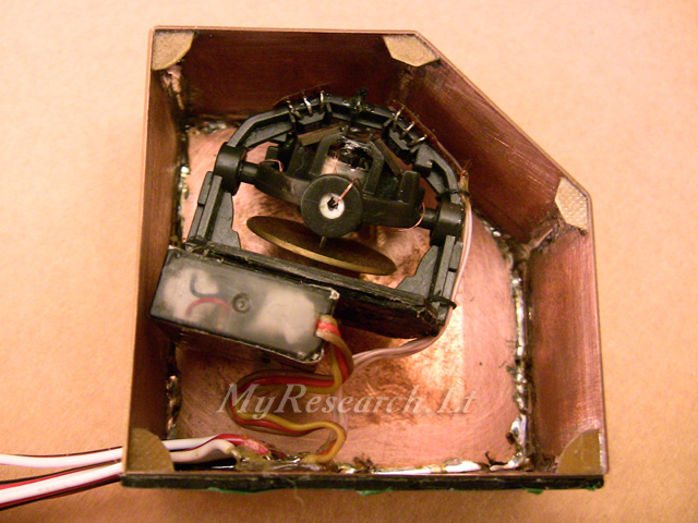
The order of installation of the extra resistors.
Take the servo-mechanism (either analogous or digital one - it does not matter) and, without connecting it to the receiver, turn the arm manually. It is necessary to get convinced that the necessary magnitude of deviation is mechanically possible. Then remove the lower cover of the servo-mechanism. The electronic scheme inside is connected with the motor and the potentiometer. Three wires come out of the potentiometer: two wires - on each side and one - in the middle. The wires, coming out of the lateral contacts, must be slit. Seeking for rotation of the servo-mechanism, which secures deviation for 120 degrees, for 180 degrees, it is necessary to install the resistors, equal to 25% of resistance of the potentiometer, between the slit ends of the wires. If the magnitude of resistance of the potentiometer is not indicated on it, the magnitude can be measured by connecting the tester to two slit wires. Usually the potentiometers for 5 or 10 kOhms are installed in the servo-mechanisms. The extreme positions of the swing can be regulated by installing the diminutive potentiometers instead of the constant resistors.
The view reflects the standard servo-mechanism out of the set of the equipment SPECTRUM. Resistance of the potentiometer is 5 kOhms; two extra potentiometers (2,5 kOhms each) are installed; the maximal deviation makes approximately 200 degrees (+-100).
It is also possible to install constant resistors, resistance of each of which will make approximately 30-35% of the value of resistance of the potentiometer of the servo. In this case the servo will be set against the mechanical limiter and it will be necessary to restrict motion of the servo in the menu of the control panel.
Increase of the angle of deviation of the servo-mechanism up to 360 degrees
If you need the servo-mechanism, rotating around without limitations for 360 degrees, then it is necessary:
a) to pull out or to grind off, or to cut off the ledge, restricting rotation, on the last gear;
b) to disconnect the potentiometer from the mechanism;
c) to switch on the servo-mechanism and to tune the potentiometer in such a way, so that the motor does not rotate in case of the neutral control signal;
d) to assemble the servo-mechanism.
Now the servo-mechanism will rotate around according to the control signal, without returning into the primary position.
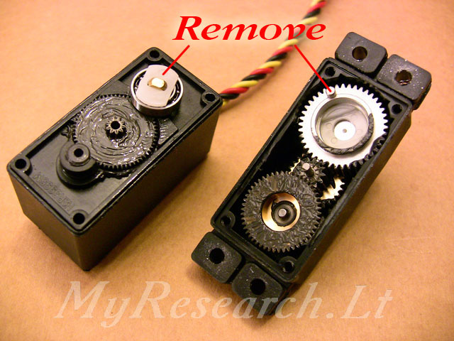
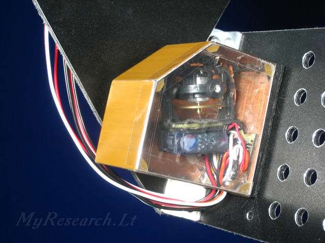
The photo reflects the gear with the restrictive ledge, which must be pulled out, and the insert, connecting the mechanism with the potentiometer, which must be removed.
Tuning of the double servo-drive for video-cameras
Double servo-drive is usable for smooth control and stabilization of a video camera. Double servo-drive eliminates free movement and enables avoiding of shake of the camera caused by operation of the electronic gyroscope. Double servo-drive can be made of two ordinary servo-mechanisms.
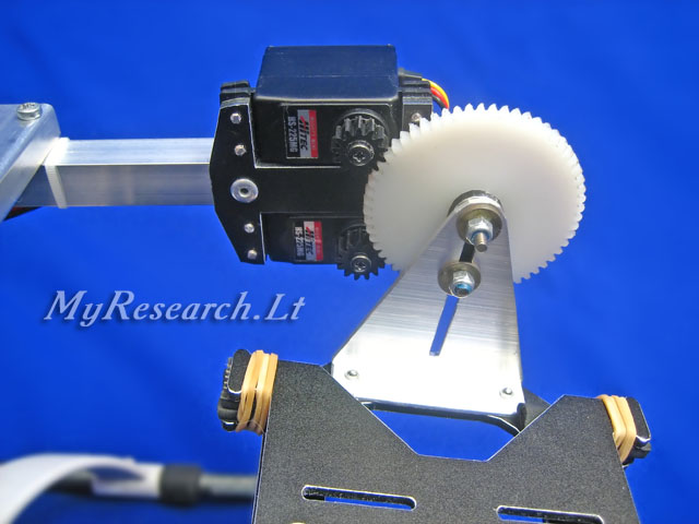
The servo-mechanisms, modified for turning for 360 degrees, are used in the camera gimbal. The both servo-mechanisms are connected to one control channel. In case of the neutral control signal, the conjugated servo must rotate slowly to the opposite sides. An electronic synchronizer may be applied for synchronizing of the servo-mechanisms. Such devices are being produced by several companies, but it is possible to manage without it. The speed of the servo without the load is fixed by the potentiometer, which is disconnected from the gears. The preliminary tuning may be done as follows: fix the control signal at -2 % from the neutral position and achieve halt of the first servo; fix the control signal at +2% from the neutral position and achieve halt of the second servo. If You have such possibility, it is desirable to measure the current, which is consumed by the servo in case of stoppage of the motor by force, while tuning. Start tuning from the low current, for example, from 20 mA. The assembled servo-mechanism without the load rotates very slowly at such current. If the heavy camera is fixed on the gimbal and its center of gravity does not coincide with the rotation axle, it will be necessary to increase the load upon the servo-mechanism artificially, seeking for stabilization. The excessive load will cause breakage of the servo-mechanism. Thus, pay more attention to the balanced condition of the whole mechanism; it must not swing as the pendulum.
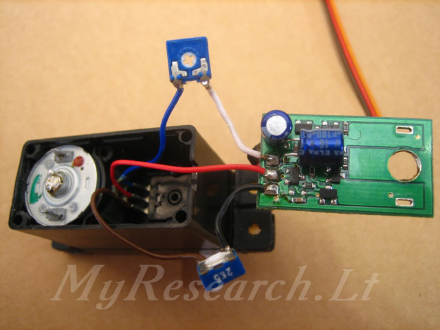
A servomechanism with a horizon sensor
Such a servomechanism is usable for controlling the bank of the aircraft or the inclination of the camera. You'll be able to control the inclination of the camera; the neutral position will conform to the horizon line. In addition, it is possible to control the ailerons of the aircraft and to incline the aircraft to the desired angle in respect of the horizon. If the horizon line is not symmetric, a bank of the aircraft appears. The scheme of the sensor:
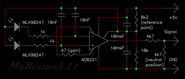
PCB: 
IR photocells are fixed on the movable part of the controlled gimbal of the camera or on the opposite ends of the controlled model. A signal of the sensor is applied to an ordinary servomechanism instead of the internal potentiometer. The potentiometer of the servomechanism is connected to the negative terminal, to the reference voltage and has one output (3 conductors); the infrared sensor is connected in the same way.
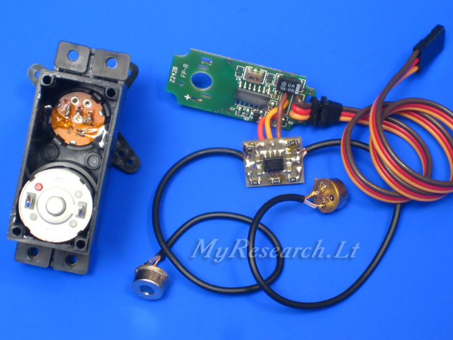
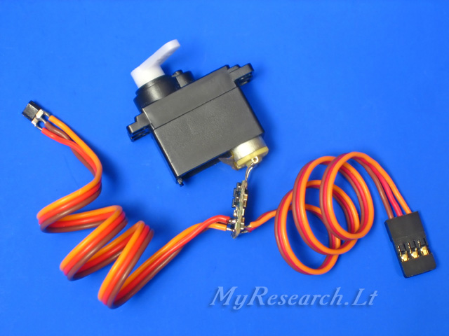
Servomechanism with a magnetic position sensor
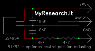
Such a servomechanism is usable for controlling various mechanizations, such as gear extension or rotation of any element via a supplemental reducer. I used such sensors for leveling-off the video camera in respect of the position of the mechanical gyroscope. A Hall sensor ensures a proportional response to a change of the magnetic field, taking into account the polarity. An absence of magnetic field or the neutral magnetic field (in case of equal distances from the opposite poles) in the transformed servomechanism conforms to the neutral position of the potentiometer in an ordinary servomechanism. The sensor responds to a shift or rotation of the magnet; it is also possible to use two magnets in two extreme positions. The scheme of connection:
The mechanical gyroscope used as a virtual horizon:
The position of the gyroscope is established by magnetic sensors. Inclination of the video camera is preset by inclination of the gyroscope:
|