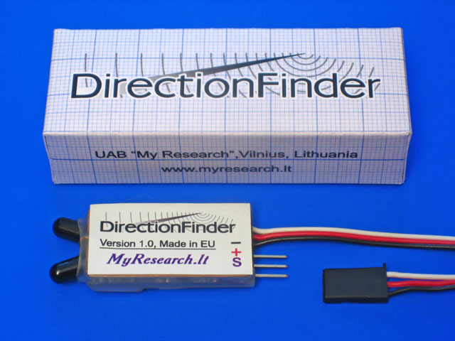
Automated pointing of the video-camera to the object, selected for shooting
DirectionFinder device can be applied for following purposes: automatic pointing of a camera towards the object of shooting; automatic persecution of the specified target; automatic prevention of a collision with the specified target. A special infrared radiator is mounted on the object to be watched by the device. Alternatively, the object can be marked by reflected radiation, for example, laser's ray. Infrared radiation is invisible for human eyes. Infrared radiation is modulated, so the device will not react to any extraneous infrared sources. The device is connected between the receiver and the servomechanism. The device can operate in the autonomous mode, without a control signal from the receiver. One device controls a single plane of rotation; so for control in the horizontal and the vertical directions, two control channels and two DirectionFinder devices are required.
The examples of application of the device: 1. The device is mounted on a radio-controlled vehicle and enables it to pass automatically through the specified gate; to persecute automatically the specified vehicle; to avoid automatically a collision with the specified obstacle.
2. The device is mounted on the active suspension of a video camera and enables the camera to keep automatically the specified object in the center of the shot.
3. The device is mounted on a radio-controlled model of an airplane and enables it automatically to fly above the specified areas or to get into recovery net.
Video:
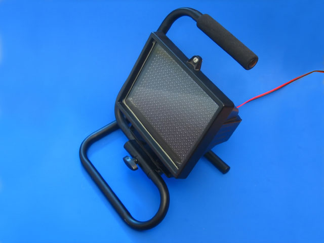
The distance of detection of the specified object depends on the power of the radiator. 20 W LED radiator (with pulse power of 50 W) of 20deg. directivity is detectable by the device in the distance up to 200 m; however, a clear response of the device is ensured in the distance up to 40 m. A rapid response to a signal of the same power reflected from a white surface is ensured in the distance up to 20 m. The term "reflected signal" should be also interpreted as a signal detected in any direction, except of the one of the directional radiator. For doubling the distance of detection, the power of the radiator should be increased 4 times (mathematical squaring). For a rapid response to reflected signal from the distance of 100 m, a 500 W radiator should be required. To increase the distance or the angle of radiation, more than one radiator may be used. Twitching of Servo with automatic guidance may be associated with a weak IR signal or scattered signals.
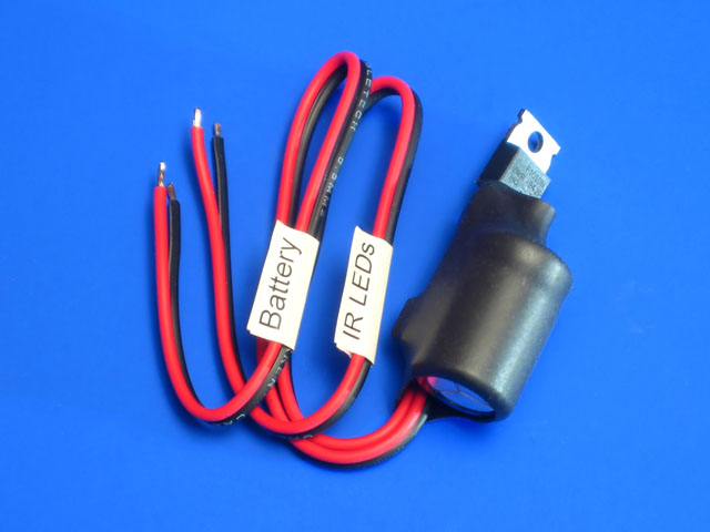
The set of the device includes an electronic scheme for modulation of the radiation of the infrared light. The choice of models of the infrared lighters is abundant. The wavelength of the light radiated should be taken into account; it should be equal to 950 nm. Feeding of the radiator should be ensured by the provided scheme. The power voltage may be 5-16V, the maximum current in absence of a supplemental heat radiator - 10A, and if a supplemental radiator is used for the transistor - 75A. Feeding of the IR light diodes in the spotlights is arranged through a resistor. Because the supplemental scheme ensures pulsed radiation, the nominal value of the resistor may be halved. So, the radiated power will be increased.
Mounting and adjustment of DirectionFinder device
The device shall be mounted in the way that ensures the direction of its sensors coinciding with the direction of movement of the model or in parallel with the video camera. If control of turning leftward and rightward is required, the sensors should be placed in the horizontal plane and should have a deflection leftward and rightward, respectively. The device detects an infrared radiator upon a deflection from the principal direction in the range up to 35 degrees horizontally and up to 17 degrees vertically (the survey field is 70x34 degrees). If possible, the sensors should be covered to avoid their contact with direct sunlight.
The servomechanism is connected to the output of the device. If a gyroscope is used, it is connected between DirectionFinder device and the servomechanism. The input of the device is connected to the remote control receiver. For adjustment of the device, the button on its case should be kept pressed on switching power supply (the remote control unit should be switched on as well). After power supply is switched on, release the button, and the LED will go out. Set the control stick to the left position (if dual rates limits are used, they should be removed) and push the button once again. The LED should blink twice. Set the control stick to the right position and push the button once again. The LED should blink three-times. Set the control stick to the neutral position and push the button once again. The LED should blink for four times. Now the degree of the response of the device, in other words, the deflection of the servomechanism needed for maintaining the required direction should be found. The button shall be pressed in five second 0 times or once or twice or 3 times. 0 times corresponds to the minimum degree of response, and 3 times - to the maximum degree of response; 1 and 2 are intermediate values. If the degree of response is insufficient, the automatic rotation will be too slow; if the degree of response is too high, the rotation will be jerky. So, the adjustment is completed. If after the adjustment, the rotation is found to be oriented to the direction from the infrared radiator, not towards it, adjustment process shall be repeated; in such a case, the extreme right position of the control stick is fixed firstly and then the extreme left position is fixed (i.e. the opposite sequence of directions takes place). If the LED flashed during operation of the device, this fact attests the radiator to be in the zone controlled by the device. If the signal is detected, the device deflects the servomechanism in the required direction. The possibility of proportional manual control is always preserved. If a deflection of the control exceeds 50%, the automatic response of the device will cancel.
The device can provide an automatic response in absence of a control signal in the input. For this purpose, feeding voltage of +5V should be applied to the device (as in a case of connection to a receiver) and the third contact of the plug-type connection (the white wire) should be remained unconnected. For adjustment of the device, the button on its case should be kept pressed on switching power supply. After power supply is switched on, release the button, and the LED will go out within 5 second. Within the following five second, reverse (a response in the opposite direction) can be activated: for this purpose, the button should be pressed once more. If reverse is not required, do not push the button. After the expiry of five second, the LED will blink twice. Now the degree of the response of the device, in other words, the deflection of the servomechanism needed for maintaining the required direction should be found. The button shall be kept pressed for five second for 0 times or once or twice or for 3 times. 0 times corresponds to the minimum degree of response, and 3 times - to the maximum degree of response; 1 and 2 are intermediate values. If the degree of response is insufficient, the automatic rotation will be too slow; if the degree of response is too high, the rotation will be jerky. After the expiry of five second, the LED will blink for three times. Then, the mode of operation of the device when a signal from infrared radiator is not detected should be selected. 0 pushing - no change of the output signal; 1 pushing - a smooth return to the neutral position; 2 pushings - fast return to the neutral position; 3 pushings - the neutral position. For automatic control of the camera, using servomechanisms with a disconnected potentiometer (the modification "360 degrees") and selection of the "3 pushings" mode are recommended. After completion of adjustment, all parameters are saved in automatic way.
Electronic scheme for modulation of the radiation of the infrared light: