    ECILOP EASY / STEREO Assembling manual and Force Servo modification Complectation (Ecilop Easy kit)
Parts & upgrades: http://www.myresearch.company/ee-parts.phtml Force Servo configuration process: http://youtu.be/WOZkC4Q6Cqk Demo flight: http://youtu.be/a0LOVGwukpQ 3D Sample: http://youtu.be/40YdmRPuosk Gimbal setup examples: https://vimeo.com/82165658 Example of configuration : https://vimeo.com/77561077 F-Servo test: http://youtu.be/4pBnEhLAtBw Accuracy test: http://youtu.be/1g3fAj4FIKs Frequently Asked Questions: http://www.myresearch.company/data/ecilop_faq.phtml Discussion thread: http://www.rcgroups.com/forums/showthread.php?t=1640731
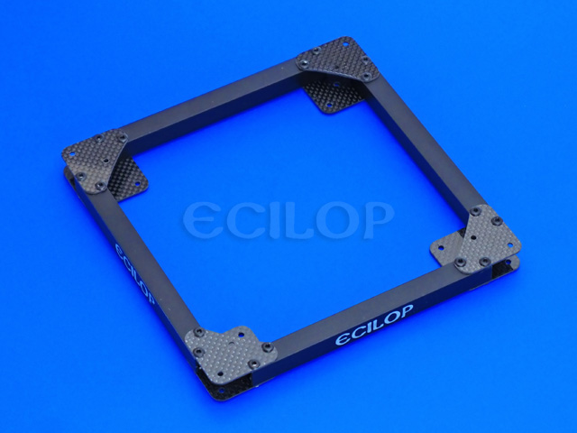
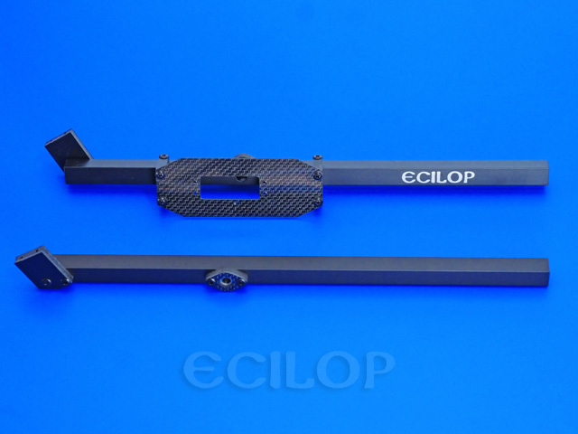
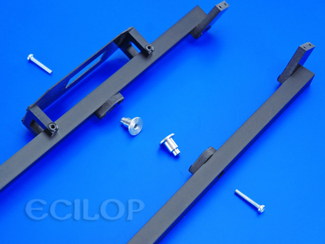
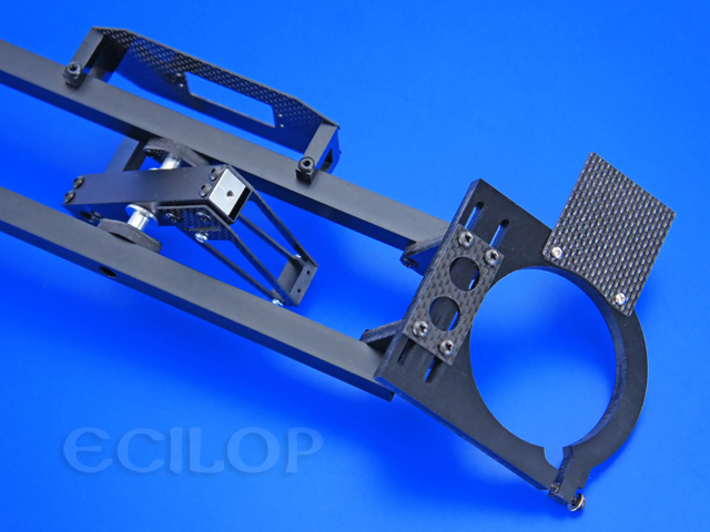
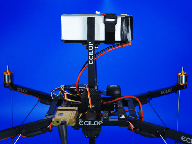
Technical data: The package contains the following items shown in the images below: Main frame
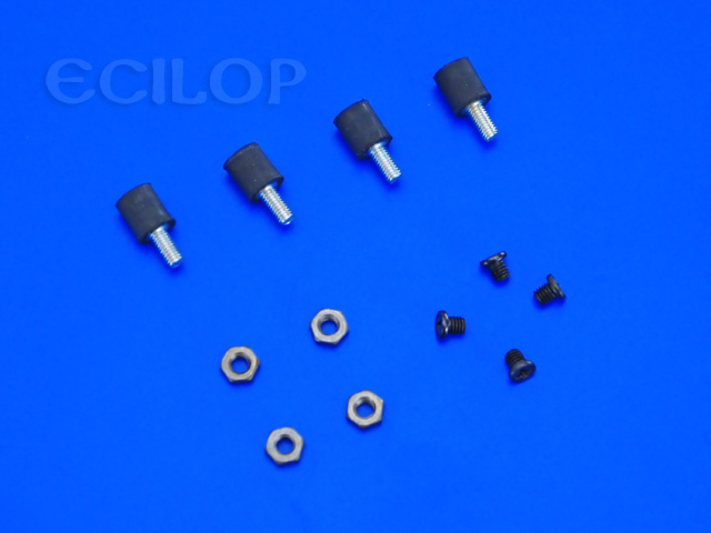
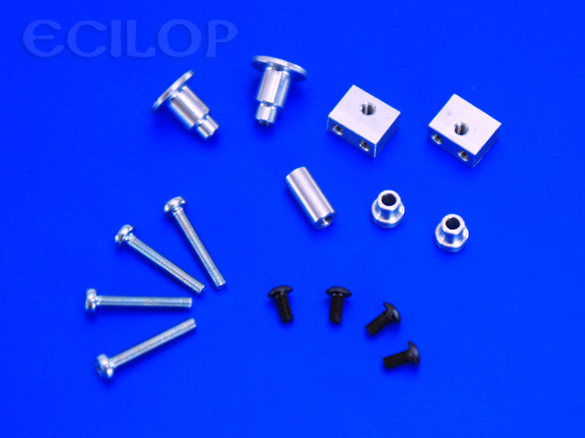
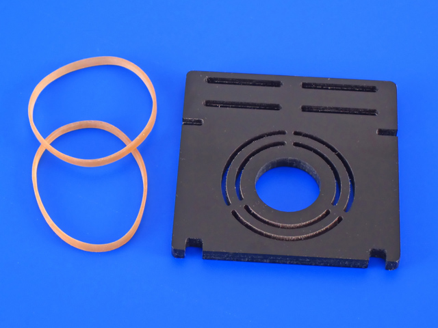
Vibration dampers
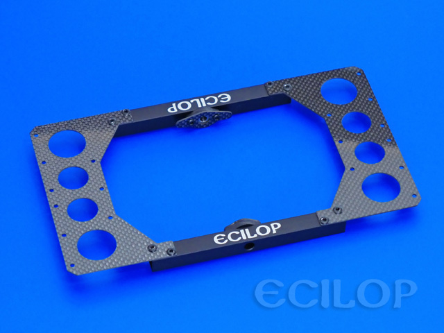
Equipment platform
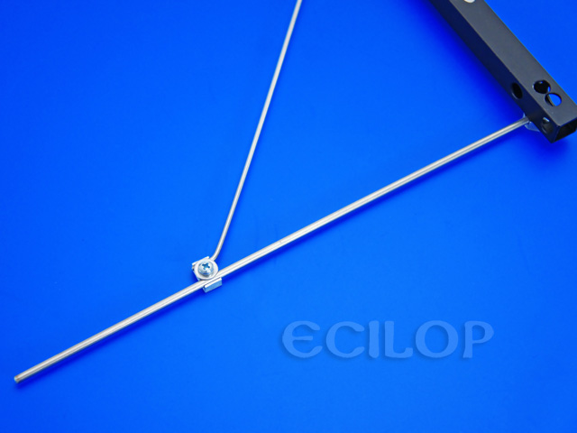
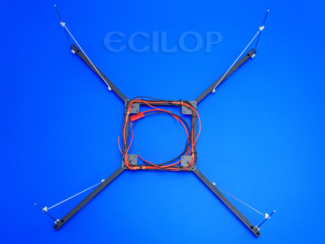
Antennas frame
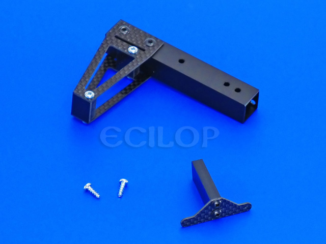
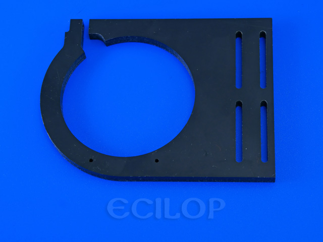
Axial unit
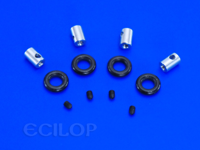
Axial fixers
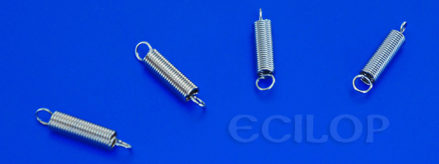
Springs 1.0 N/mm (default)
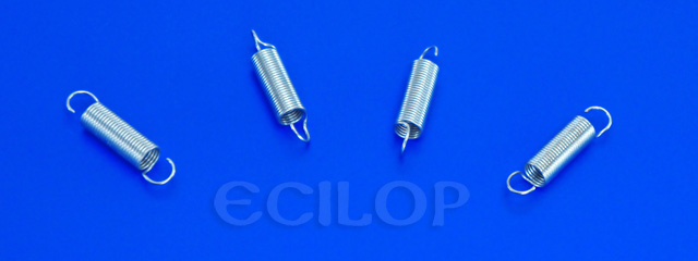
Springs 0.4 N/mm (weak)
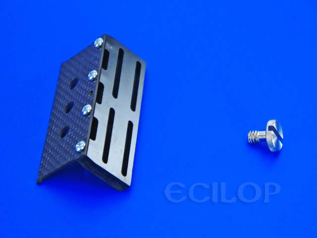
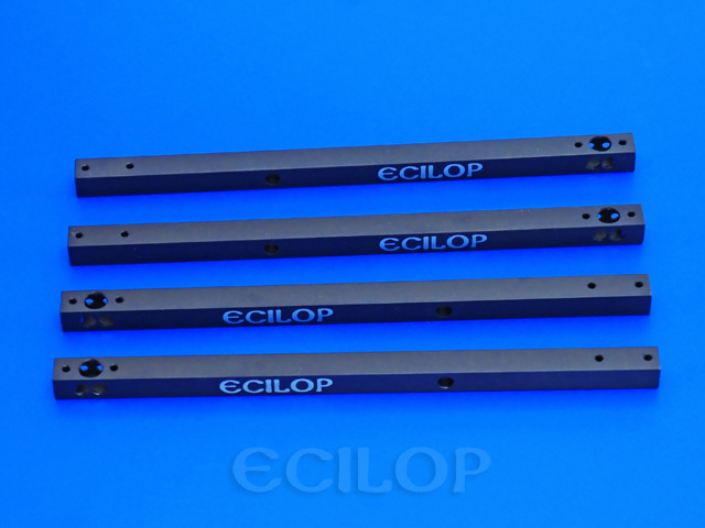
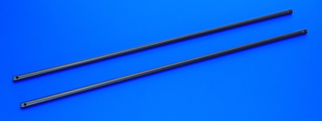
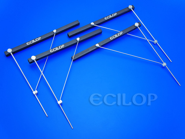
Balance beam stands
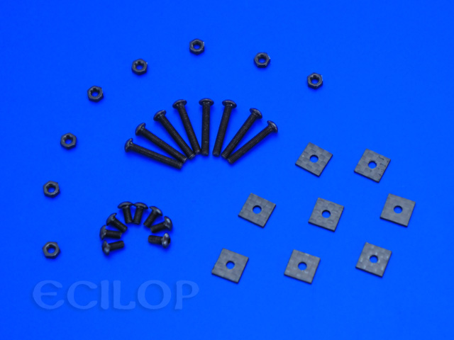
Servo screws
Camera mount screws
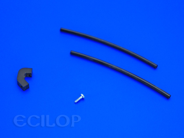
NEX camera lock
NEX-7 camera lock
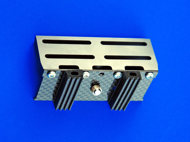
Tripod type camera fixer (upside down)
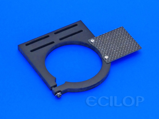
Small camera fixer
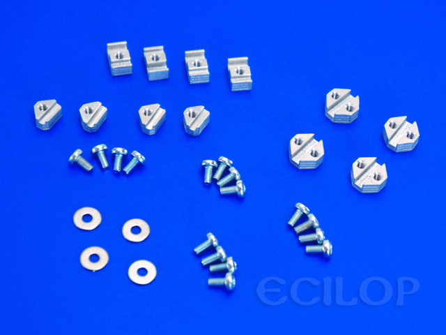
Battery platform 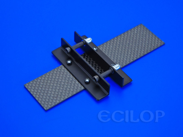 Engine stands
Engine fixers
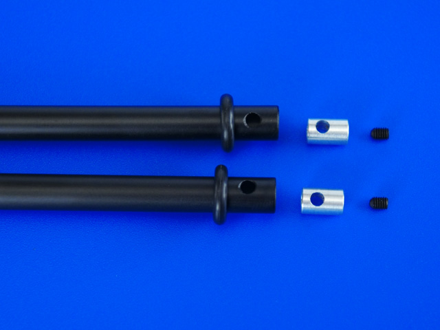
Chassis stands
Chassis fixers
Landing skids
Skid fixers
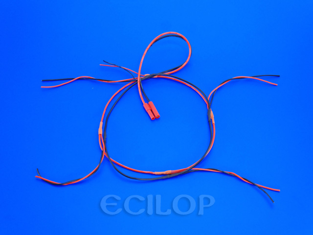
Power disribution wires
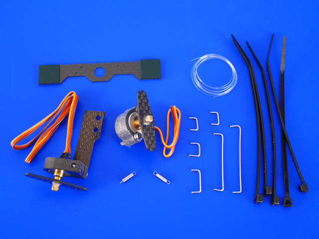
Force servo modification parts
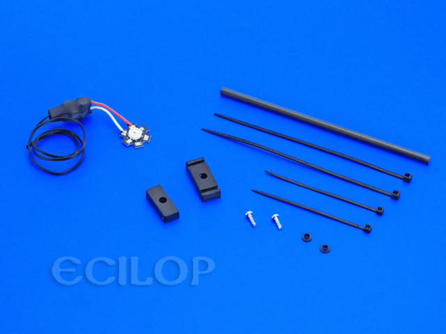
Tail LED
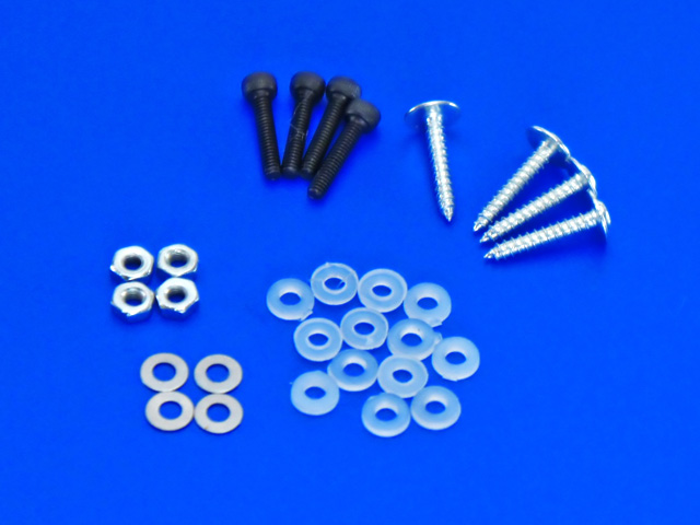
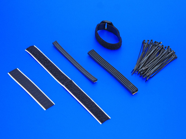
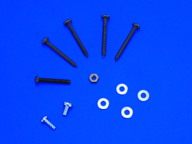
Fixture elements
Spare parts
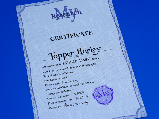
Certificate
You will need the following additional components (not included): A digital camera (Sony NEX-x is recommended); Assembly instruction Install the camera tilt axis lock into the axial unit.
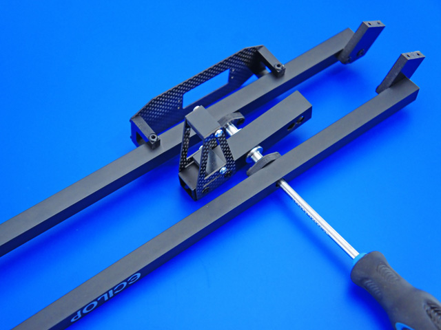
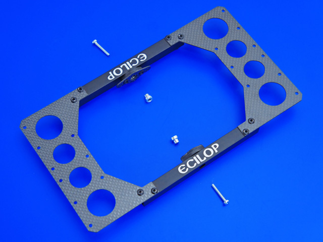
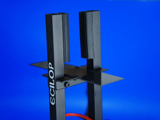
Fasten two balance beam stands using two screwdrivers on its opposite sides. Medium strength threadlocker must be applied.
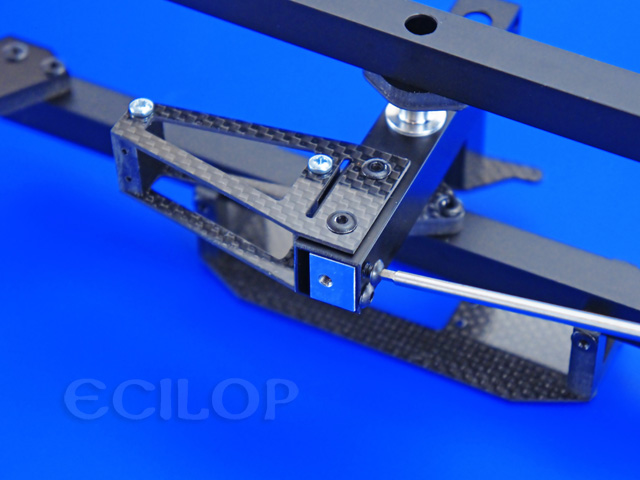
Use bolts to fasten two fixers of the camera's second tilt axis. Use moderate torque.
Fasten the springs holder.
Fasten the camera lock, but leave the bolts a bit loose.
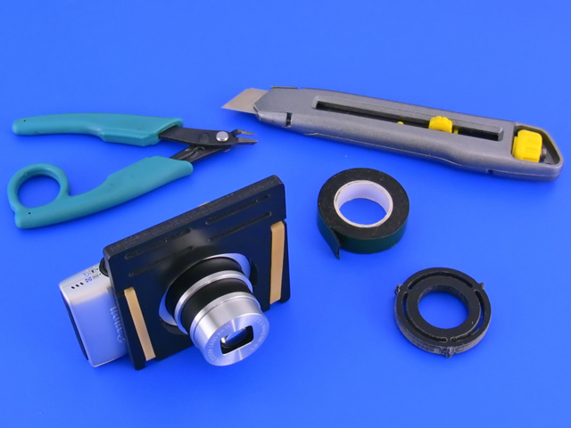
The universal camera fixture allows you to install any camera on the drone. The camera is fixated with a regular tripod screw and should be flipped vertically. The ratio of the mass of the camera to the mass of the battery should be in the range of 0.9 - 1.35 (mass of the camera divided by the mass of the battery). It is not recommended to use cameras heavier than 600 grams.
This camera fixture allows you to install any small camera on the drone.
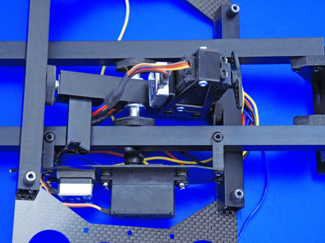
Prepare a modified Force Servo drives. (information is listed below) Install and fasten the servo gears. Install under the servo nylon washers to increase the gap if neaded.
Attach dampers to the equipment platform using nuts. Medium strength threadlocker must be applied.
Bolt up the axial unit to ball bearings on the equipment platform. Use washers if you need to fill the gaps. Medium strength threadlocker must be applied.
Loosen the bolts on the locks and tighten them up again. This operation will help you eliminate the slight deviation of the locks from the rotation axis. Medium strength threadlocker must be applied.
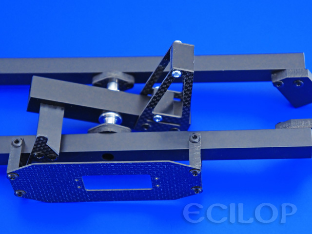
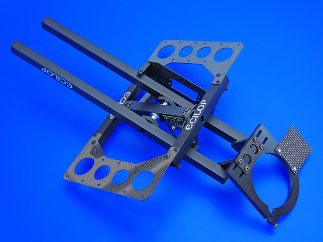
Bolt up the chassis stands to the engine stands.
Bolt up the engine stands to the main frame. Notice the holes on the sides of stands: 6 mm holes must face forward and backward, while chassis stands must be oriented to the left and to the right. Medium strength threadlocker must be applied.
Put rubber rings on the landing skids. Install the chassis stand locks into the landing skids. Use an epoxyde or cyanoacrylate adhesive to hold them in place.
Fasten the landing skids on the chassis stands. Medium strength threadlocker must be applied.
Attach the electronic equipment platform to the main frame. Hold the rubber dampers with pliers when screwing the bolts. Medium strength threadlocker must be applied.
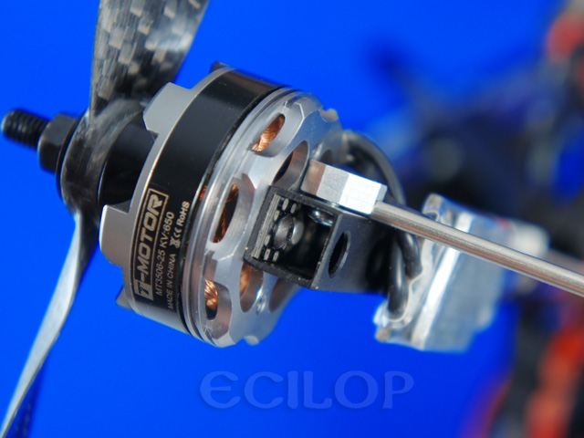
Bolt up the engines. Medium strength threadlocker must be applied.
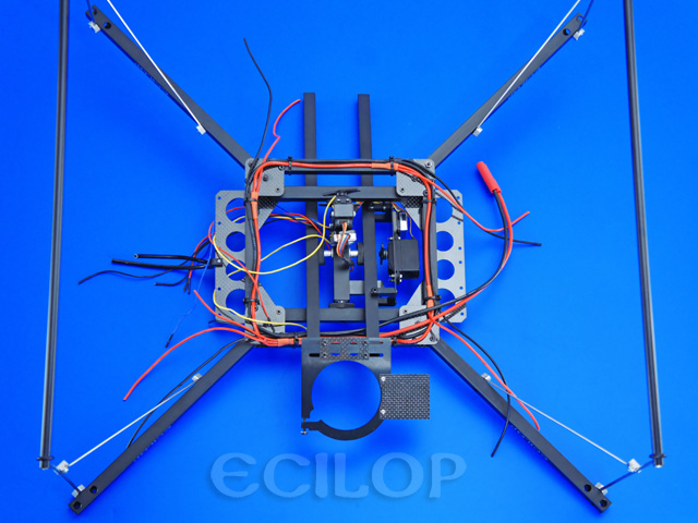
Assemble and fasten the frame for the receiver's antennas.
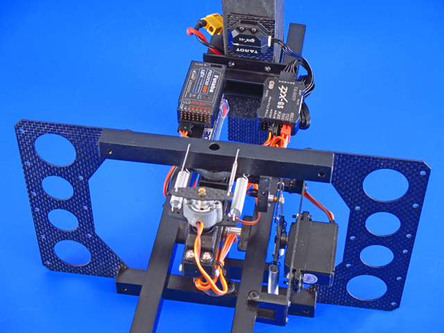
Install the electronic equipment: a receiver, an autopilot, speed controllers, gimbal controller, a voltage stabilizer, an OSD module, a video transmitter. The servo-mechanisms are connected to the gimbal controller, the controller is connected to the receiver. Wires must not rub or tap into gyroscope. The cables connecting the moving parts of the drone must be soft and bent into a loop. The cables must pose minimal obstruction to the rotation of structural elements. Use a separate power switch for onboard electronics.
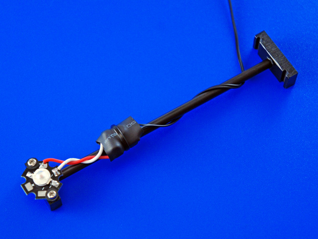
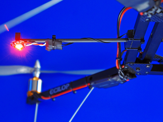
The LED is powered through an inverter. 3S-5S Li-Po battery can be used as a power source. Connection polarity does not matter. Power soutce: 11-24V AC/DC. 1. Assemble the LED mount using cyanoacrylate glue. Screw on the LED using isolation washers.Fixate the LED mount and wires on the aircraft frame. Connect to the power source.
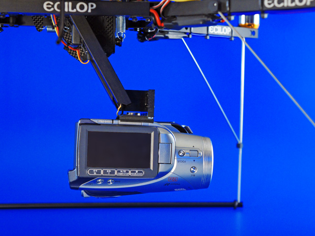
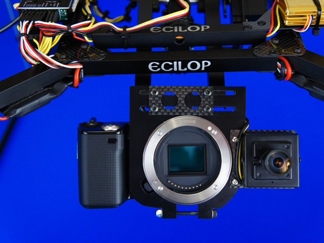
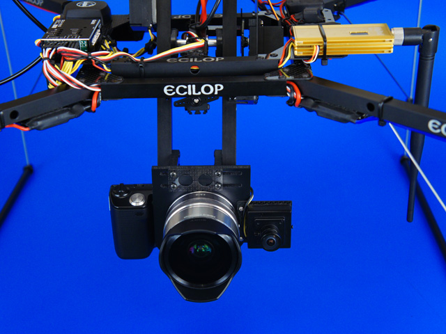
Take the lens off the camera. Fasten the camera body on the gimbal. Install the lens.
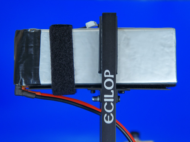
Install the battery platform on the balance beams. Glue the soft edge padding to the balance beam stands to ensure close contact with the battery. Select thick or thin spacers, depending on the thickness of your battery.
Use peel-n-stick bands to lock the battery in place. To help the battery cable bend, move the battery connector from the cable to the body of the battery.
Put the drone on the side. Move the battery along the balance beam stands to achieve a perfect balance. Lock the battery platform in the necessary position.
Put the drone on the landing skids. Move the battery forward and backward to reach acceptable balance in the lengthwise direction. If necessary, turn the battery platform. Mark the right fixation position on the battery. Always use identical batteries.
Loosen the camera lock bolts. Move the camera left and right to reach optimal balance in the lateral direction. Lock the camera in the necessary position.
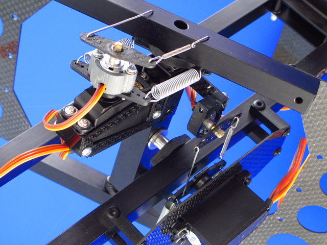
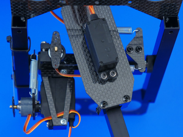
Install the springs between the servo gear and the frame.
Configure the electronic equipment as specified in the manual for your additional equipment. Install all the servos, springs and links as shown in this video. Make sure that all joints can be rotated easily, are not jammed and are not rubbing against each other.
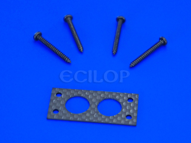
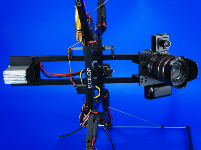
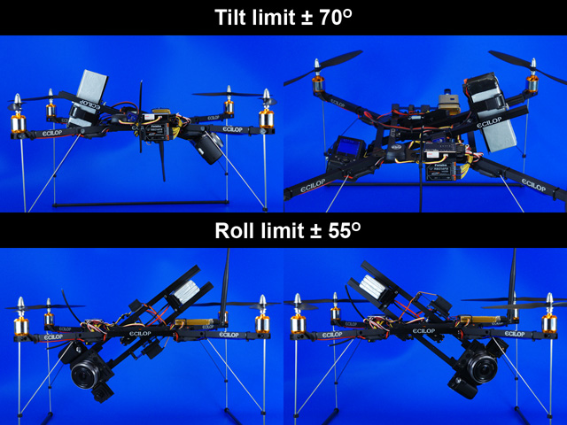
Install the rotors and check the drone in mid-air. You can detach the landing skids and engine stands for transportation. Dihedral angle gasket (optional part) Thanks to the engine tilt, the camera's vertical field of view is increased. The tilt also makes the aircraft more stable. However, the effect of this stabilization is very weak compared with active stabilization found in any multi-copter. Spacer size - 25x12x3mm; Distance between mounting holes - 19mm; Diameter of the center hole - 7.5mm; Dihedral angle - 6deg. 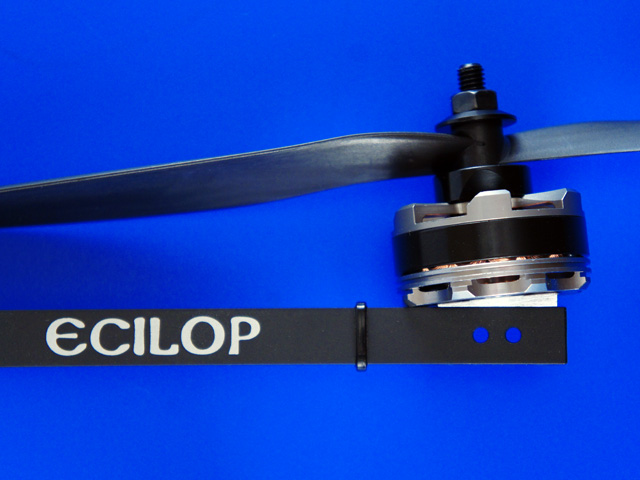
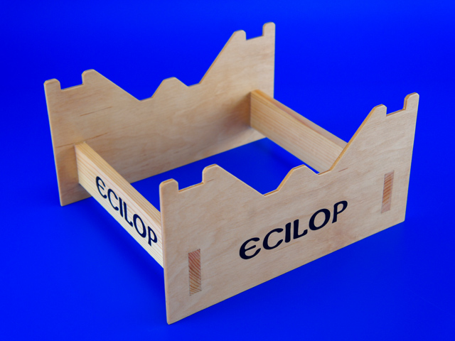
To assemble the Ecilop Stereo, use the instructions for assembling Ecilop Easy. For storage and transportation, glue together the wood stand (use wood glue). You can varnish the stand after it has been glued.
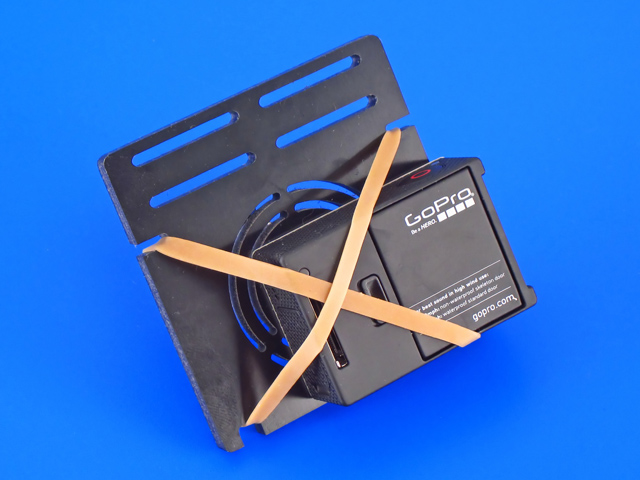
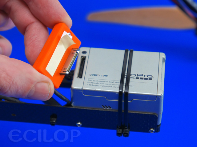
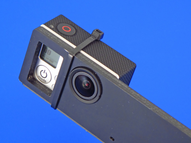
The GoPro cameras are attached to the platform with straps. The camera synchronization cable must be extended to 35 cm.
Use slim double sided sticky tape for fixing camera socket.
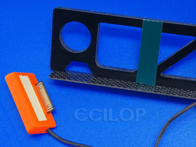
I recommend sticking soft gaskets of 1 mm thickness as it is shown on the picture. Thanks to those camera directions will intersect in approximately 7 m. distance.
How to work with two cameras without a synchronization cable. Manually enable recording on both cameras. Clap loudly before starting. Once finished, import both videos into a single SONY Vegas Movie Studio project. Soundtrack visualization will help synchronize the two files. After synchronization, join both channels into a single one in a stereo mode.
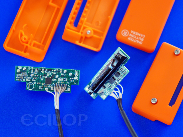
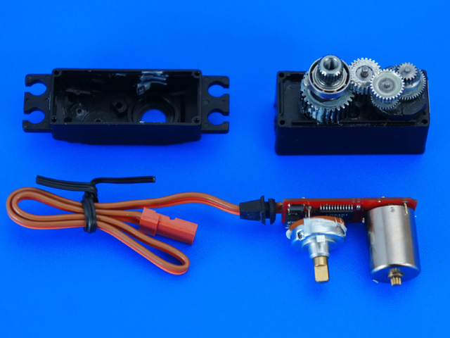
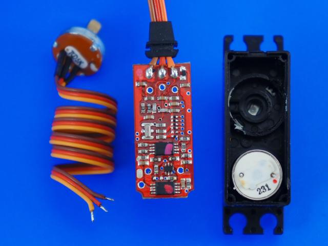
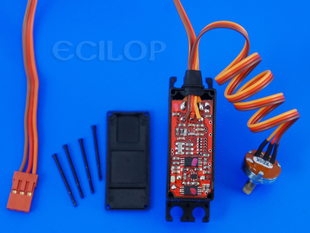
1. Dismantle the servo drives and unplug the internal potentiometers.
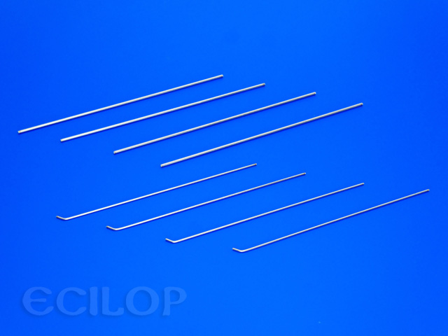
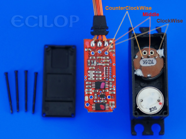
2. Note the position of contacts of the original potentiometer in the servo drive. Solder the wires of external potentiometers paying attention to wire colors (see the image for reference). Do not turn the servo on until the fishing line or metal rods are not fixed (p. 7)
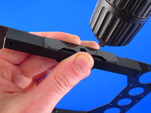
3-A. Installation of the Force Servo with a metal rods. Drill a 1mm holes in the equipment frame (if you have an older frame).
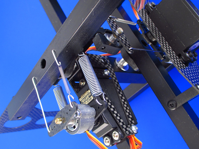
Install all the servos, springs and links as shown. Make sure that all joints can be rotated easily, are not jammed and are not rubbing against each other.
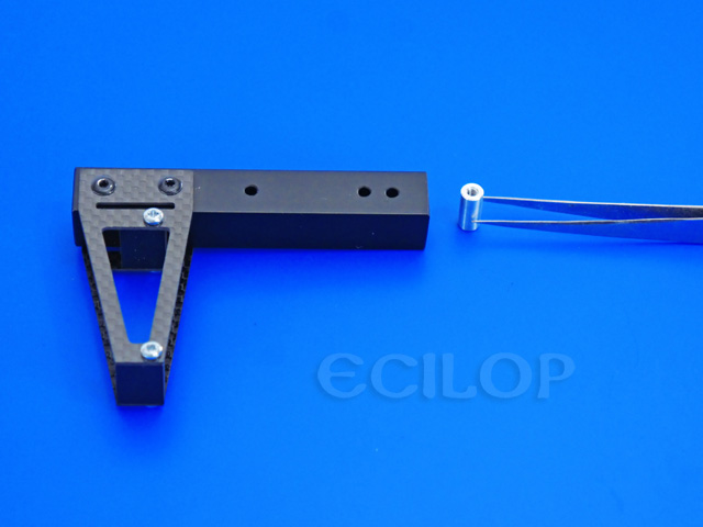
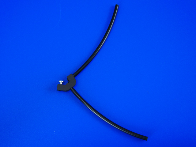
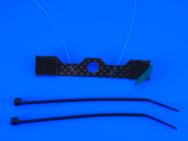
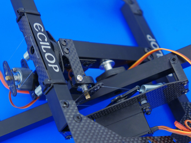
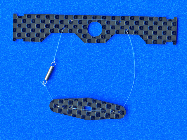
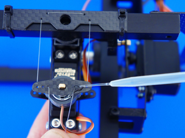
3-B. Installation of the Force Servo with a fishing line (alternative solution). Fasten the line fixture onto the frame.
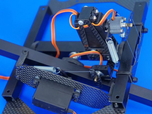
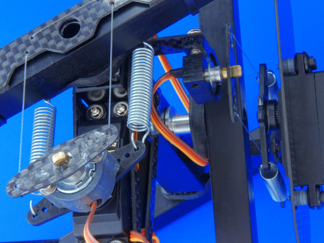
4. Fasten the potentiometer on the arm of the Roll axis servo drive (2mm drill may require).
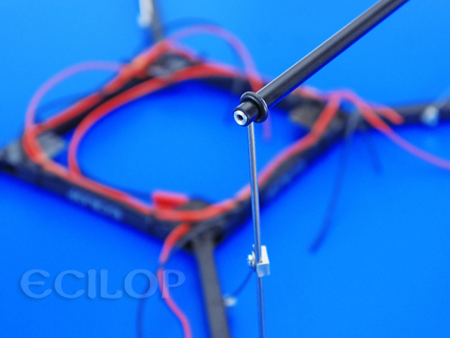
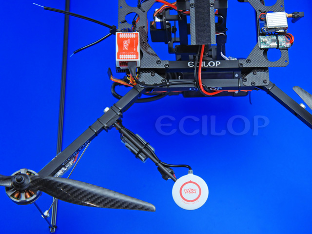
5. Fasten the potentiometer on the axial block of the Tilt axis.
6. Tie the ends of the line to the spring. The spring is installed only on one side of the arm. The spring must be stretched to be 15-25mm long (free length - 10mm). * With time, the line may stretch and the tension will be gone. To prevent this from happening, you need to install a spring that will guarantee constant tension.
7. Pull the line through the holes in the arms. Balance the potentiometer arm. Tighten the line and secure the loose end with a drop of instant glue.
|