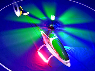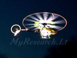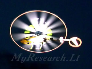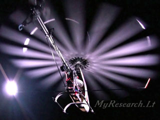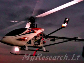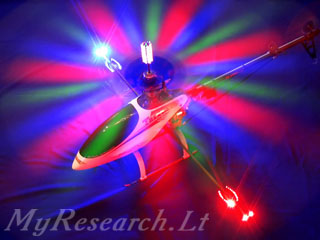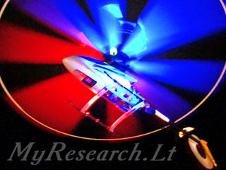   
The night lighting for R/C helicopter HeliStrobe device is installed in R/C model of helicopter and controls operation of lighting elements on the sides of the model. Lighting elements are bright LEDs directed towards the rotor and the body of the model. The sequence of flashes controlled by the microcontroller provides an image of an immovable figure formed by the rotor. The shape of the figure is chosen from 15 various versions. The image of the model brightly lighted in the both sides in night is the same as in daytime. A change of the colour of lighting causes a change of the colour of the model.
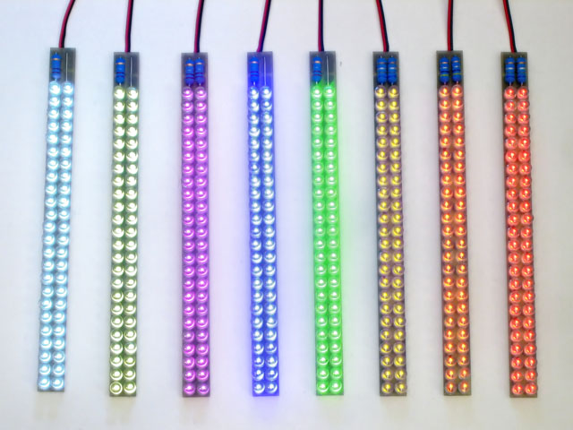
Video: HeliStrobe demonstration. 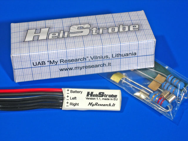 The majority of the suggested solutions, assigned for the night lighting of the model, secure its contour lighting. The contour lighting is secured by the installed light-illuminating diodes and the light-illuminating strips. The gadget HeliStrobe is assigned for the external lighting of the helicopter model. It means that the light-illuminating elements are installed in such a way so that the illuminating light gets reflected from the body and from the revolving rotor. When the body of the model is lighted from the outside, the model at night looks similarly as during the day-time. Seeking for more vivid lighting of the body of the helicopter, the light-illuminating elements are moved to the sides of the body with the help of the masts. The gadget HeliStrobe synchronizes winking of the light-illuminating elements with the rotor revolving; thus, the rotor of the helicopter looks like a solidified figure. The shape of the figure to be illuminated is selected from several preliminary set variants. The blades of the main rotor should obligatorily be of the while color Choosing of the light-illuminating diodes The bright LED's are used as the light-illuminating elements. The recommended total power of the diodes should be at least 10 W. Usage of the light-illuminating diodes of different colors changes the color of illumination of the rotor and of the body of the model. The ready-made blocks of the light-illuminating diodes, assigned for the fixed voltage, can be used. However, some of these blocks produce illumination, which is too dim, in spite of the fact that sufficiently powerful diodes are contained in them.
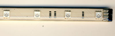
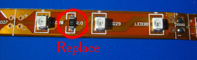
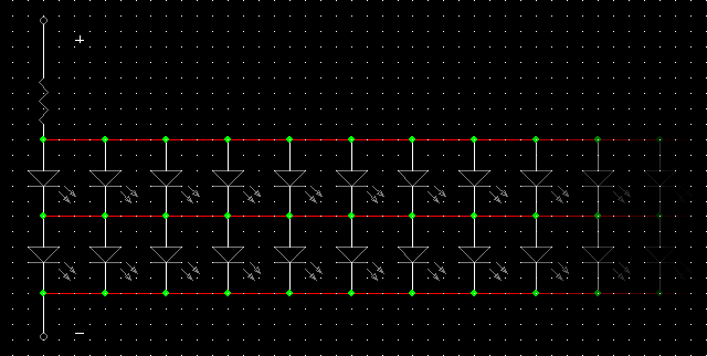
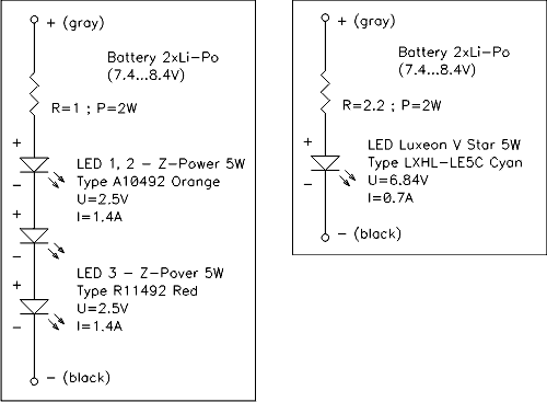
As feeding of the diodes from the gadget HeliStrobe is impulsive, the current, which passes via them, can be increased. Seeking for increase of the current, it is possible to use feeding from the battery with higher tension than it is indicated in the light-illuminating elements. For example, the section of the light-illuminating diodes, meant for 12 V, can be fed from the battery of the Li-Po accumulators, consisting of 4 sections (15-17V). As regards the gadget HeliStrobe, the permissible tension of feeding is 7-20V. In most cases the resistors, installed in the lighting elements, provided with the light-illuminating diodes, may be substituted. For example, the resistors, installed on such tapes, may be substituted by the nil ones (white color LED's, 11.1V Li-Po battery):
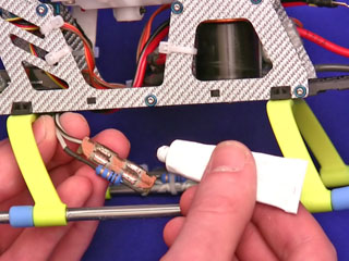
By increasing the current, You will increase brightness of illumination of the diodes, but You will hasten their expiry date. If the current is too high, the light-illuminating diodes will firstly get overheated and afterwards will burn out. Extra cooling is necessary for certain powerful light-illuminating diodes. Such light-illuminating diodes can be tightly pressed to the metal components of the landing skid, which will diffuse heat. Seeking for better heat dissipation, it is necessary to grease the connection with the heat-conducting liniment or with the special glue or to use the heat-conducting pads.
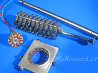
The information about connection of powerful light-illumination diodes via resistance is submitted in the manual of the gadget. It is more convenient to purchase the LED's in special shops, which sell radio-components. Manufacturers of High Power LEDs: Using panels of 48 Flat Top diodes with 5 mm diameter was found to be the most convenient and economic solution.
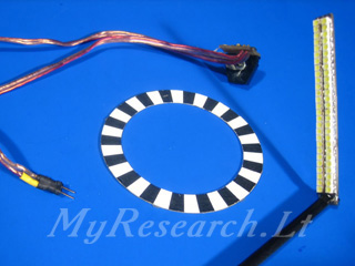
Dimensions - 161x12x8 mm, weight - 17 g. Power is supplied to the diodes via the single resistor.
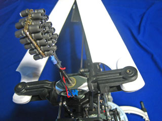
If the LEDs are fed from 7.2-8.4V battery, they are connected as follows: Improvements Seeking for illumination of the main rotor of the helicopter from above, it is necessary to fix the block of LED's over it.The feeding wires are let through the hollow axle with the purpose of installing the lighting elements over the main rotor of the helicopter. The brush collector is installed from below. The brushes of a small electric motor are used. The junction, meant for connection of the LED, is installed from above. The light-illuminating diodes, installed above the rotor, are fed from one of the outlets of the device HeliStrobe (parallel connection to one of the lateral lighting elements).
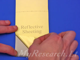
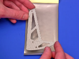
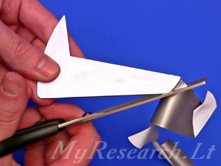
It is also possible to use the blades with the installed light-illuminating diodes so as to observe the plane of rotation of the screw propeller in the overturned condition. The demonstrative video-clip provides several examples of illumination and twinkling of the parts, pasted over with the light-reflecting film. The source of the twinkling light was fixed on the video-camera.
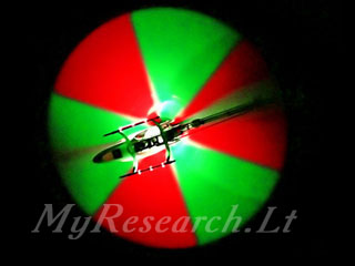
The demonstrative clip provides the view of the rotor of one of the helicopters, which is illuminated with the red-green symbol of "radioactivity". It is done in the following way. The green light-illuminating diodes are connected to the left canal of the HeliStrobe from the left and the red light-illuminating diodes - from the right. The green light-illuminating diodes are connected to the right canal of the HeliStrobe from the right and the red light-illuminating diodes - from the left. The double-color figure is achieved as the result of signals, coming to the left and right canals by turns.
History of making the gadget HeliStrobe The first version of the gadget foresees usage of the optical sensor for synchronization with the rotor. The illuminated figure used to comply with the view on the disc, which was fixed on the gear. The number of strips on the disc was divisible by the transmission number for the tail rotor; the tail rotor also looks like a solidified figure for this reason.
The second version foresees usage of the xenon lamps. The flash of the xenon lamp is very short; thus, the blades look like as if they are set in the place. The xenon lamps should be thoroughly handled; high tension should be available.
The third version foresees illumination of the rotor with many-colored light-illuminating diodes. The light-illuminating diodes revolve together with the rotor. The three-phase generator of the current, fixed on the shaft of the main rotor, used to generate feeding for the light-illumination diodes. The number of the colored petals at the illuminated rotor is equal to half of the number of magnets in the generator.
The micro-processor device serves as the fourth version. Small weight is typical of this version; it provides the possibility of selecting various figures, assigned for illumination of the rotor. All the above-specified versions of the gadget have been patented, but the non-commercial reiteration of the schemes by private persons is welcomed. Video:
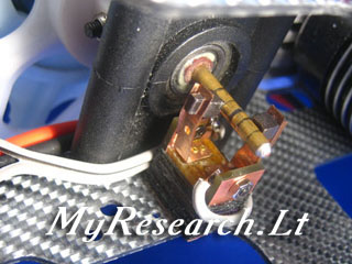
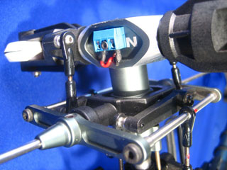
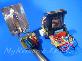
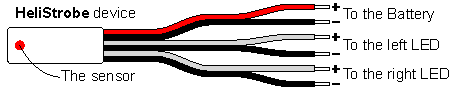
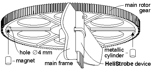
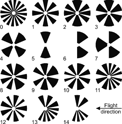
Description of the device The device is installed in the same body with a rotation sensor for the rotor. It should be installed under or over the gear fixed on the axle of the main rotor. A magnet is glued into the gear, and the sensor of the device responds to shifts of the magnet. The location of the sensor on the device is marked with the red sign. This plane of the device should be faced towards the magnet. The gap between the magnet and the sensor should be 2...4 mm. For fixing the magnet, a hole of 4 mm diameter is drilled in the gear. Before fixing the magnet with adhesive, a response of the sensor to it should be checked up; if it is absent, the magnet should be turned and its opposite end should be inserted. A metal cylinder is glued from the opposite side of the gear, seeking for the balance preservation; its diameter is identical with the magnet. The sensor and the magnet should coincide when the main rotor's blades are oriented along the body of the helicopter. After having selected the precise position, the sensor is fixed on the frame of the helicopter with the help of the double-sided sticky tape and the ties. Two feeding wires of the red (+) and black (-) color, outstretching from the device, are to be connected to the feeding connectors or to the switch. The range of the feeding voltage can vary between 7 and 25 V (two to six sections of lithium accumulators). Please, observe the polarity while connecting power supply. The lighting elements are connected to the wires, marked as “LEFT” and “RIGHT”. The white wires - the plus of feeding; the black wires - the minus of feeding. After switching-on, light appears for a short time; then it will appear after five seconds. After the second switching-on, the device can operate. Lighting will appear on rotation of the rotor only. For choosing another shape of lighting the rotor, disconnect and reconnect power supply of the device. After the first switching-on the light, turn the rotor manually for three times during five seconds. Then, after three short flashes, you can choose a shape of lighting. You'll choose a desirable shape on rotating the rotor; each revolution is accompanied by a short appearance of light. The number of revolutions varies between zero and fourteen. If you stop rotation, three short appearances of light will follow after five seconds and the chosen shape of figure will be set. All shapes selectable are provided below. If You wish to turn the figure at 180º, then exchange positioning of the left and right light elements. The duration of operation with a battery depends on the capacity of the battery and the power of the lighting elements. The maximum load current is 5A and if the feeding voltage is 20V; they ensure power of 100W for each of two lighting channels. Such power is sufficient for 2000 ordinary LEDs on each side! We recommend using superbright LEDs of maximum power to ensure the summarized power of 10-20W.
The device HeliStrobe, the view from the side of the sensor (the label is on the opposite side).
The scheme of installation of the device.
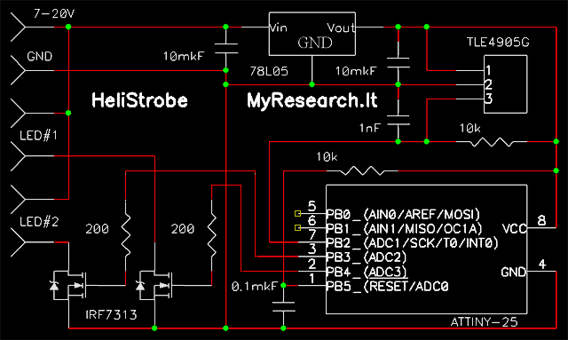
The images of figures formed by the lighted rotor. The numbering of the figures starts from 0, not from 1, that corresponds to the number of revolutions of the rotor required for choosing a shape of the figure. Technical data The set: Choosing and installing the lighting elements The example of calculation of a lighting element: Examples of the connection schemes:
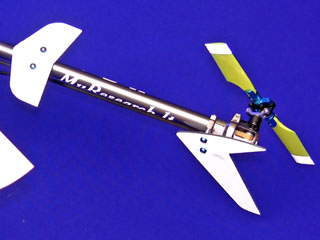
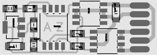
The lighting elements can be fixed to the landing skids - in such a case, the plane of the rotor is lighted very well and the body is lighted partially. To ensure a better lighting of the body, elements can be fixed to a skid fixed aside the body. The skid is made of a carbon tube 1 m long and with the external diameter of 10 mm; the thickness of its walls should be 0.5-1 mm. A tube of a less diameter can vibrate considerably. The center of the tube should be fixed to the frame of the helicopter, and the lighting elements oriented towards the main rotor and the body of the model should be fixed to its ends. Schematic: PCB: Aleksey Zaitsevsky, 2008, http://www.myresearch.company
Tags: helistrobe, heli strobe, helicopter lightning, heli light, night flying, night flight, flying at night, RC lightning, model illumination, light kit, night flyer, LED lighting, lighting system, navigation lights, LED flasher |